In order to implement your design, we need the output in conventional format generated by the CAD programme.
We prefer to use an intermediate format, for greater privacy and security for our customers. By doing so, a complete project will not have to be put on the net, effectively nullifying any copyright risk.
Data type
The most commonly used and conventional formats are:
– Gerber RS-274X (Extended Gerber with built-in apertures – developed by Gerber systems)
– ODB + + (OpenDatabase + + – developed by GenCAM)
– DPF (dynamic process format – developed by Ucamco NV)
for drilling instead:
– ODB + + (OpenDatabase + + – developed by GenCAM)
– In Gerber RS-274X or RS-274D format (only drilling data, not any maps)
– DPF (only drilling data, not any maps)
– Excellon (1 or 2) with text file with drilling diameters (preferably embedded and not external)
Using these formats allows automatic loading and correct recognition at the import stage;
native CAD formats are not supported by our systems.
Please contact us at info@mypcbstore.de for any further information; we may be able to help you with Eagle or KiCAD files.
Once you have generated your data, create one (1) compressed file (zip. or .rar) and make sure you:
– Have only one (1) version of your project within the compressed file
– Do not use any folder or folder structure, so that our systems and operators can read the data without any possibility of doubt or ambiguity.
– Identify the compressed file with a unique and meaningful name referring to your project or order.
Which data to provide
In order to ensure correct import and order handling within the given timeframe, it is important to provide ONLY the data files required to produce the PCB as below:
– Copper sides
– Soldermask sides
– Screen printing sides
– Drilling
– Board edge
– Any mechanical sides
– Any solder paste sides
– Any additional sides (carbon/peltable/dissipation)
Make sure that any instructions or specifications are clear and present.
If it is unavoidable to add additional explanatory files, make sure that these files are in ASCII format or a common format (e.g.
.PDF or .doc).
It is recommended to check the result of the Gerber generation process with one of the many free Gerber file viewers available on the web.
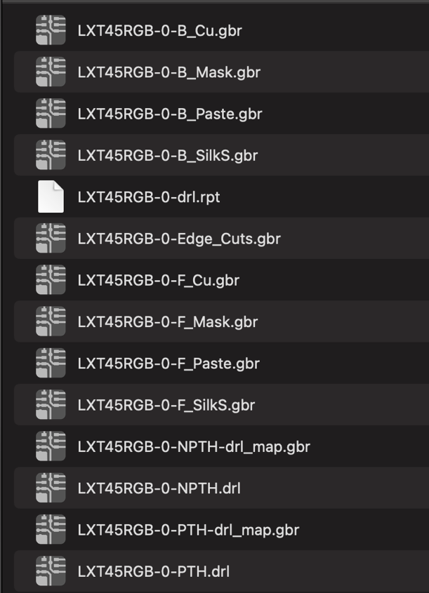
Data file names.
For naming data files, use clear and easy-to-understand file extensions and avoid long or convoluted names.
Make sure any operator can recognize and assign the correct function to the files.
Some useful examples:
When using the **automatic check** you must follow the instructions in the following guide; otherwise the server may return an incorrect figure or no result at all.
Panel
If you need to receive panel cards with one or more figures, you have the option of using the “create panel” editor to instantly build and visualise your idea, inserting or adjusting the strips to your liking or the CS numbers.
If you already have a panel, there is a special “provide panel” editor where you only have to enter the maximum dimensions and the
number of pieces.
It is very important and mandatory that the panel you have designed is then inserted in a viewable format (gerber 274x, ODB++, pdf, dxf)
within the complete zip.
It will also be possible to configure single-circuit delivery.